You've got OpenSCAD installed, and you know your way around the window — the viewport, the editor pane, how to spin the camera without getting lost. Now it's time to actually put something in that empty space.
There's no main() -- and variables aren't quite variables
If you've written code in almost anything else, you're probably expecting a file to need some kind of starting point — a main() function, a begin block, something that says "the program starts here." OpenSCAD doesn't have one. A file that contains nothing but this:
cube(10);is a complete, working OpenSCAD program. Save it, open it, and you'll see a 10mm cube. There's no wrapper required around it.
What actually happens is simpler than it looks. Every shape you write at the top level of the file — meaning it isn't stored inside a variable and isn't sitting inside a module you defined but never called — gets drawn, and everything drawn gets combined together automatically, as if it had all been wrapped in one invisible union. There's no "print the result" step you're missing. The geometry on screen is the output.
Where this gets genuinely confusing — and it will, the first time it happens — is variables. In most languages, a variable can be reassigned as the program runs: code above a second assignment still sees the old value, and code below it sees the new one. OpenSCAD doesn't work that way. Write this:
x = 5;
translate([x, 0, 0]) cube(2);
x = 10;
and the cube does not end up at x equal to 5, but at x equal to 10 — because in OpenSCAD, the last assignment to a name in a given scope wins for that entire scope, including the code written above it. There's no sequence of "first it was this, then it became that." There's just one final value, decided by whichever line was written last, applied everywhere that name is used. It's a small rule, but it's the one that causes real head-scratching later, so it's worth having it clearly in your head before you write a single shape.
Three shapes you'll use for almost everything
Nearly every design starts from the same three building blocks.
cube(size) — a box. Give it one number for a cube with equal sides, or a list of three, [x, y, z], for a rectangular block. By default the corner sits at the origin; add center = true and the whole box straddles the origin instead, which is usually what you actually want once you start combining shapes.
sphere(r) or sphere(d) — a ball, sized by radius or diameter. Spheres are always centred on the origin.
cylinder(h, r) or cylinder(h, d) — a cylinder (or a cone, if you give it r1 and r2 instead, two different radii for the bottom and top). Like the cube, it sits with its base at the origin unless you add center = true.
Two 10mm cubes make the difference concrete:
cube(10);                      // corner sits at the origin

translate([15, 0, 0])
cube(10, center = true);   // this one straddles the origin instead
Same size, same shape — the first one has a corner planted at [0, 0, 0] and grows away from it in the positive direction; the second is centred on wherever you translate it to, five millimetres of material on either side of that point along each axis.
That center flag is the single most common source of "why is my shape in the wrong place" for anyone starting out. When two shapes don't line up the way you expected, it's worth checking that first.
Getting two shapes to meet
Two commands do almost all the positioning work you'll need. translate([x, y, z]) moves whatever comes after it. rotate([x, y, z]) spins it, in degrees, around each axis. Both wrap the shape they apply to, the way parentheses wrap an expression:
translate([10, 0, 0])
    sphere(d = 6);
moves a 6mm sphere 10mm along the X axis. Stack them and they apply in order, outside-in — so translate then rotate then cube rotates the cube first, then moves the rotated result.
Three ways to combine solids
This is where OpenSCAD stops feeling like drawing and starts feeling like specifying. You don't sculpt a shape by pushing and pulling material — you describe two or more solids and tell OpenSCAD how they relate to each other. If you ever sat through a Venn diagram in school, you already know these three operations — they're not a similar idea borrowed for 3D, they're the literal same set operations, just applied to solid shapes instead of circles on a page:
union() — everything inside becomes one combined solid. Overlapping regions just merge.
difference() — the first shape listed, minus everything after it. This is how you cut holes, slots, and pockets.
intersection() — only the volume that every listed shape has in common. It's the one you'll reach for least often, but it's the right tool when you need "wherever these two shapes overlap and nowhere else."
The difference operation earns its keep immediately. A block with a hole through it:
difference() {
    cube([40, 20, 10]);
    translate([20, 10, -1])
        cylinder(d = 8, h = 12);
}
Notice the cylinder is taller than the block (12mm through a 10mm-thick block) and starts 1mm below it. That's deliberate, not sloppy — the cutting tool needs to poke out both sides of what it's cutting. Two solids that end exactly flush against each other can leave a wafer-thin sliver of ambiguous geometry along that seam; a cutting tool that clearly sticks out past both faces never leaves any doubt about what's being removed.
Why a number needs a name
That example works, but look at it again: 40, 20, 10 describe the block. 20, 10 again describe where the hole goes — dead centre, which only works because you did the arithmetic in your head and typed in the answer. Change the block's width and the hole is off-centre until you go back and redo that arithmetic, everywhere it appears.
This is the point where a plain number stops being enough, and it's why variables show up this early rather than being saved for "later." Give the dimensions names instead:
block_w = 40;
block_l = 20;
block_h = 10;
hole_d  = 8;

difference() {
    cube([block_w, block_l, block_h]);
    translate([block_w/2, block_l/2, -1])
        cylinder(d = hole_d, h = block_h + 2);
}
Nothing about the geometry changed. What changed is that the hole is now defined relative to the block — always centred, always poking through cleanly — no matter what the block's width or height become later. Change one line at the top, and the rest of the file simply follows. This isn't the full parameterization story yet — lists, and building reusable modules out of your own shapes, are worth a post on their own — but this much, on day one, is the difference between a one-off sketch and something you can actually keep working with.
Building something real: a pen cup
Put all four ideas together — primitives, positioning, booleans, and named variables — and you can build something you'd actually print. A simple cup: a hollow cylinder for the body, with a wider disc underneath so it doesn't tip over.
wall_t  = 3;   // mm -- thickness of the cup wall
inner_d = 50;  // mm -- clear inside diameter
height  = 80;  // mm -- cup height, base included
base_d  = 70;  // mm -- base disc diameter, wider than the cup for stability
base_h  = 4;   // mm -- base disc thickness

union() {
    cylinder(d = base_d, h = base_h);  //A

    translate([0, 0, base_h - 0.1])
        difference() {
            cylinder(d = inner_d + wall_t*2, h = height);  //B
            translate([0, 0, wall_t])
                cylinder(d = inner_d, h = height);  //C
        }
}
Three cylinders, marked A, B, and C above. Here's how they fit together:
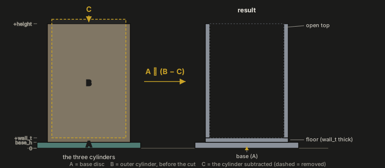
B minus C is the cup itself — an outer cylinder minus a slightly narrower, slightly shorter inner one, leaving a solid floor wherever C hasn't started cutting yet, and thin walls wherever it has. A is a separate disc, unioned on underneath, wider than the cup for stability. Notice C is placed a fraction higher than B's own bottom, and pokes out a fraction above B's own top — the same idea as the cutting tool poking through the block earlier, just applied top and bottom this time: two solids that only touch along a single shared face can render as a technically-valid-but-fragile seam, while overlapping them by a fraction of a millimetre fuses them into one solid with no ambiguity at all. It's a habit worth having from the first object you ever build, not something to retrofit later.
Change the inside diameter and the wall thickness, the outer diameter, and the base all stay in proportion. That's the whole point of naming the numbers.
Where this leaves you
None of this is complicated in isolation — three shapes, three operations, and a handful of numbers with names instead of just values. What it adds up to, though, is a genuinely different way of thinking about a design: not as a sequence of actions performed on material, but as a description of what the finished solid is, in terms simple enough that changing your mind about one dimension doesn't mean starting over. Everything after this — modules, lists, the more elaborate tricks — is really just more ways of saying the same kind of thing more efficiently.