Part 1 covered getting OpenSCAD installed. This part covers what you're actually looking at once it opens — the window layout, what each pane does, how to find your way around the 3D view, and the difference between the two buttons you'll press most: Preview and Render.
OpenSCAD's window is built from up to five panes, and unlike most software, every one of them is optional — you can hide, resize, undock into a floating window, or rearrange any of them from the Window menu.
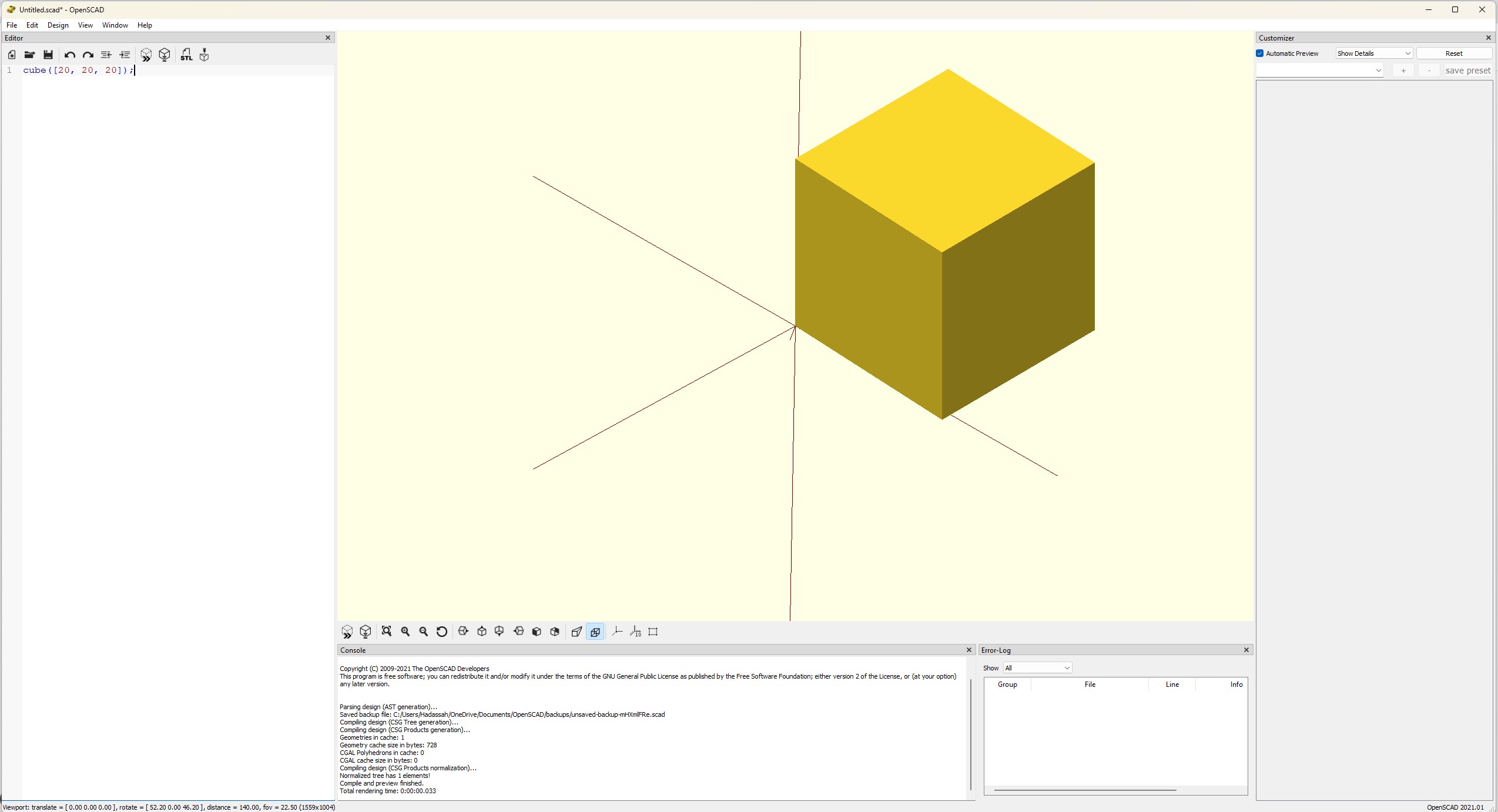
1. Editor (usually left) — a plain text pane. This is where the model actually lives — OpenSCAD has no drag-and-drop shape tools; everything is typed. It has syntax highlighting and bracket-matching, similar to a code editor, but it's not doing anything more than displaying and editing text. 2. Viewport (usually center/top, the largest pane) — the 3D preview. Whatever the editor describes shows up here once you ask OpenSCAD to build it. 3. Console (usually bottom center) — this is your feedback channel. Warnings and render statistics land here. If a model looks wrong or nothing appears at all, this is the first place to look — check it before assuming the geometry itself is broken. 4. Error Log (usually bottom center/right) — this is your other feedback channel. Errors land here. 5. Customizer (usually far right, hidden by default) — turns certain variables in your script into an interactive form: sliders, dropdowns, checkboxes. Useful once a model has parameters worth adjusting without editing code directly — not something you'll use on day one, but worth knowing it's there. Toggle it from Window > Customizer.
None of these positions are fixed — drag a pane's header to any edge of the window to redock it, or click the small window icon to pop it out entirely. If a pane ever goes missing, the Window menu is where to bring it back.
## Moving around the 3D view
There's no separate "orbit" tool to select — the viewport always responds to the mouse the same way:
- Left-click and drag — rotate the view around its center point - Right-click and drag (or another mouse button, depending on your setup) — pan, shifting the view without rotating - Scroll wheel — zoom in and out
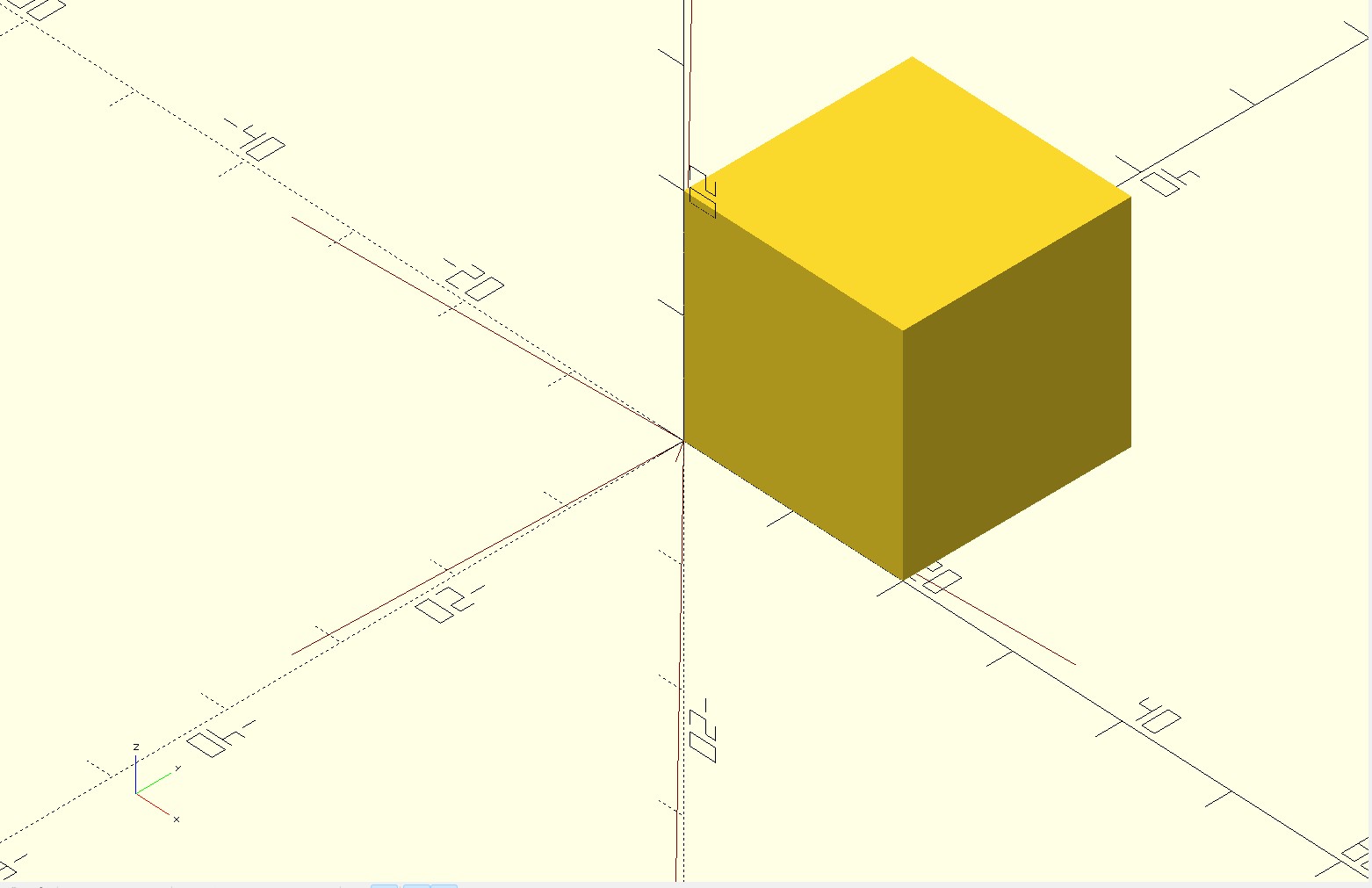
The little axis indicator in the corner of the viewport (toggle it via View > Show Axes) is worth leaving on while you're still building spatial intuition for the coordinate system — it tells you which direction is which as you rotate.
## The View menu — where you'll actually spend your time
The mouse gets you rotating and panning freely, but the View menu is where you jump to a known position instead of hunting for one by hand. It's easy to overlook early on, but it's genuinely one of the most-used menus once you're working regularly.
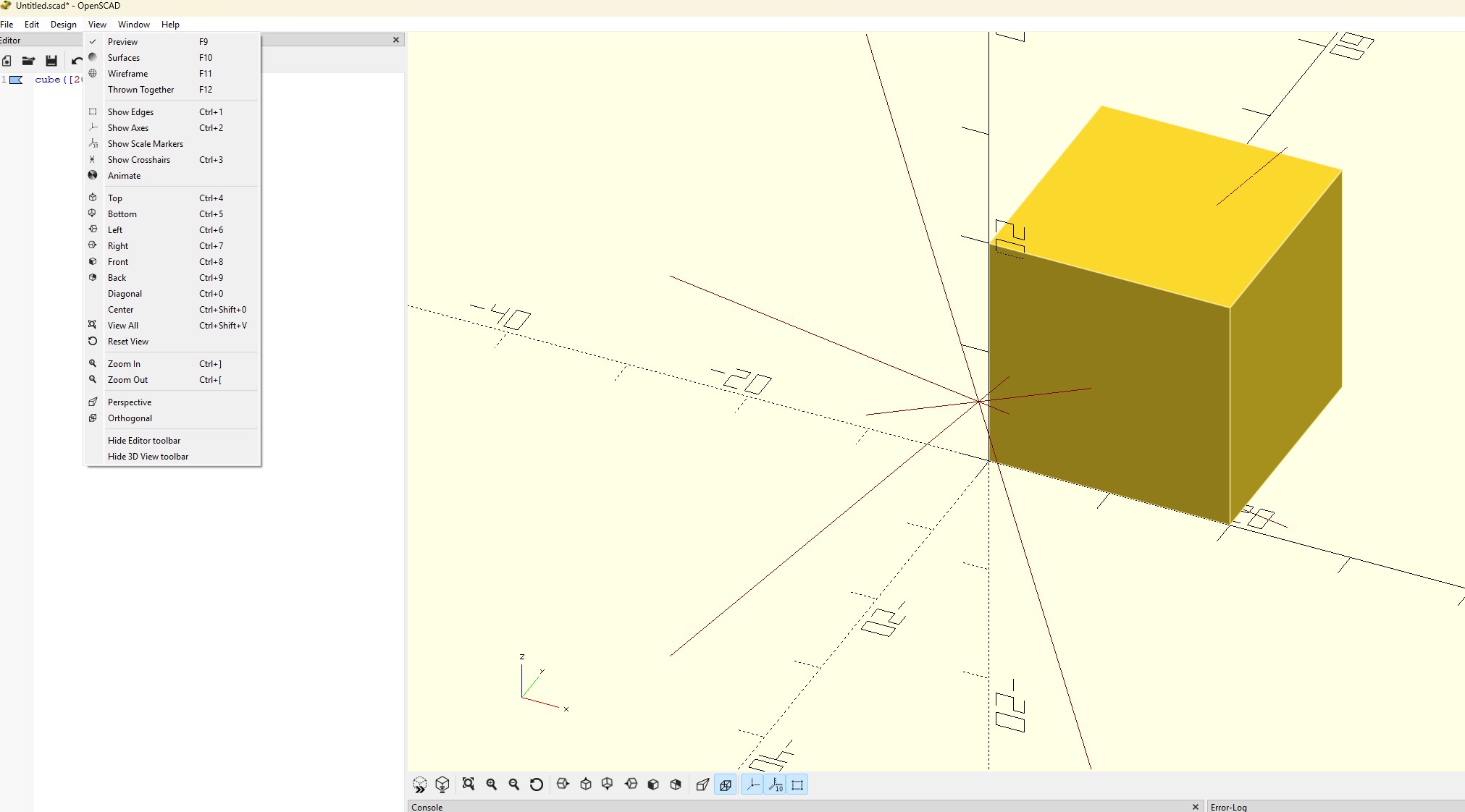
You'll notice a key combination listed to the right of most entries — that's the keyboard shortcut for jumping straight to that command without opening the menu at all. A few worth knowing from day one:
- Top / Bottom / Left / Right / Front / Back / Diagonal — snaps the camera to a fixed, aligned angle instantly. Diagonal is the default angle OpenSCAD opens with. - View All — recalculates the camera so the entire model is framed in the viewport. If you ever rotate or scroll your model off-screen, this is how you get it back. - Show Axes — the coordinate indicator mentioned above. - Show Edges — outlines the edges of faces, which makes it much easier to tell where one surface ends and another begins, especially once models get more complex than a single cube. - Perspective / Orthogonal — toggles between a perspective camera (closer things look bigger, like a photo) and an orthogonal one (no distortion, parallel lines stay parallel — useful for judging whether something is actually the size or shape you think it is). - Animate — opens an animation bar along the bottom of the window. Not something you'll need for a static print, but worth knowing it's there if you ever want to preview a model changing over a parameter range.
Worth spending five minutes clicking through each alignment option once, just so the names stop being abstract — "Front" and "Right" mean nothing until you've seen where they actually point relative to your model.
## Preview vs. Render — the distinction that trips people up
This is the one piece of OpenSCAD's interface that genuinely isn't obvious coming from other software, and it's worth understanding early rather than discovering by accident.
- Preview (F5) — a fast, approximate view of the model. It's good enough to check that geometry looks roughly right, but it's not the real, final mesh — some visual glitches at the seams where shapes combine are normal in Preview and don't mean anything is wrong. - Render (F6) — the real computation. This builds the actual, final mesh using a proper solid-geometry library rather than the fast approximation. It takes noticeably longer — sometimes much longer on a complex model — but it's the only mode that shows you what will actually export correctly.
A plain cube doesn't have any color assigned, so here's a more detailed model to make the difference obvious:
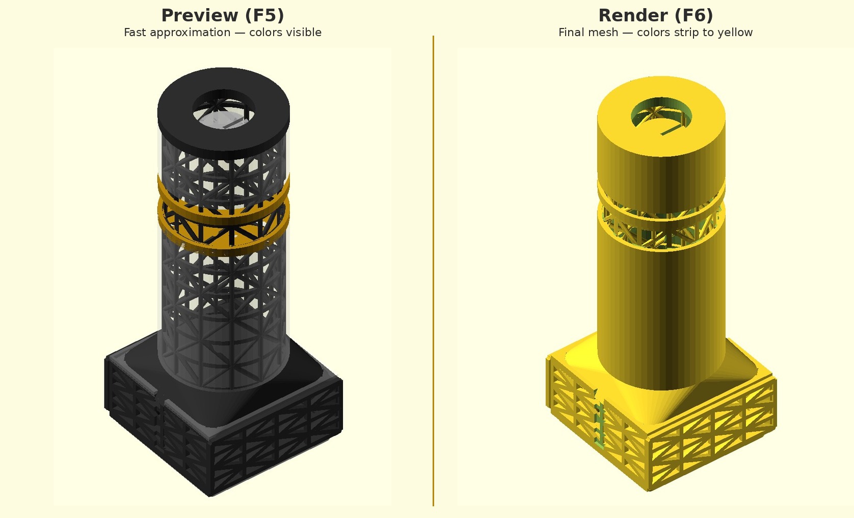
Day to day, Preview (F5) is what you'll hit constantly while iterating on a script. Render (F6) is what you run before exporting an STL (the exported file — or files — used for printing) — never export straight from a Preview-only session.
## A first shape, just to see it move
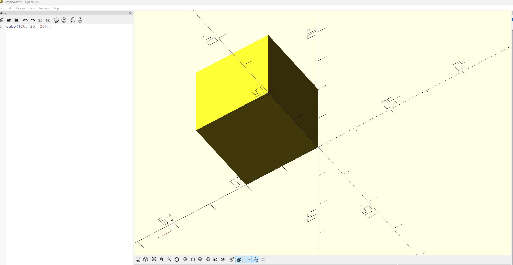
None of this needs explaining in depth yet — that's what the rest of the series is for — but typing one line into the editor makes everything above concrete instead of abstract:
``` cube([20, 20, 20]); ```
Press F5. A 20mm cube appears in the viewport. Rotate it, zoom into it, and it'll behave exactly as described above. That's the entire loop this software runs on: describe a shape in text, preview it, adjust the text, preview again.
## The cheat sheet — bookmark this now, not later
OpenSCAD publishes an official cheat sheet — a single reference page covering every built-in shape, transformation, and function, each linked through to the full manual entry. It's available two ways:
- Online, permanently, at openscad.org/cheatsheet - From inside the program itself, via Help > Cheat Sheet
There's no reason to rebuild this from scratch or hunt for a third-party version — the official one is comprehensive, kept current with the software, and free. This is genuinely the single most-used reference for anyone working in OpenSCAD regularly; worth keeping open in a browser tab for the next several posts in this series, since upcoming parts (parameterization, then modules and boolean operations) will lean on exactly the syntax it documents.
—-
That's the interface. Nothing on this page does anything clever yet — one cube, five panes, a menu for getting to any angle instantly, two ways of looking at the same shape. The next part in this series is where it starts getting interesting: turning fixed numbers like that `20` above into variables, so a single script can produce a whole family of related shapes instead of just one.